|
|
| ІъЖ·ЧКБП | јјКхЧКБП | СщАэ№ӨіМ | ІъЖ·Зэ¶Ҝ | ІОҝјЙијЖ | УҰУГөзВ· | НЁС¶РӯТй | К№УГЛөГч | Ц§іЦИнјю | КэҫЭІйСҜ | ОКМвҪвҙр | ұкЧј·Ё№ж | НјКйЧКБП | »щҙЎЦӘК¶ |
|
ЎЎ |
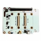
Stream Board
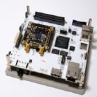 Stream is a flexible platform for developing high-performance digital and RF designs using an Altera Cyclone IV FPGA and Lime Microsystems FPRF transceiver. The board incorporates SDRAM, Micro SD storage and a selection of other useful peripherals, with expansion via RFDIO and FMC mezzanine cards enabling use with both Myriad-RF 1 and LMS7002M EVB RF modules. An OpenRISC SoC is available for Stream that is capable of running Linux and bare metal applications, complete with a peripheral controller for interfacing RFDIO cards such as Myriad-RF 1. This allows for a mixed development model whereby programming and control is done via a flexible RISC processor, with baseband processing taking place directly in the FPGA fabric. Software is provided for use with the LMS7002M EVB that allows control of the transceiver, ADC spectrum to be analysed via an FFT viewer, and example waveforms to be loaded into the FPGA. FPGA 1ЎўCyclone IV EP4CE40F23C7N device in 484-pin FBGA 2Ўў39ЎҜ600 LEs 3Ўў1134 Kbits embedded memory 4Ўў116 embedded 18ЎБ18 multipliers 5Ўў4 PLLs 6ЎўJTAG mode configuration 7ЎўSerial mode configuration via Cypress FX3
RAM and storage 1Ўў2x64MB (16bit) 2ЎўSDRAM Micro SD with access via USB Host controller
Interfaces 1ЎўMicrel KSZ9021GN GbE controller 2ЎўDual USB 2.0 host (VNC2-48L1B) 3ЎўCypress FX3 USB 3.0 (CYUSB3013) 4ЎўDVI transmitter (TFP410)
Expansion 1ЎўFPGA Mezzanine Card (FMC) LPC connector 2ЎўRFDIO (FX80P) high-speed connector 3ЎўGPIO header
Programming and debug 1ЎўFPGA JTAG header (Altera USB-Blaster) 2ЎўCypress FX3 JTAG header 3ЎўMictor E5346A Agilent test equipment connector
Clock system 1Ўў30.72MHz oscillator 2ЎўProgrammable clock generator (SI5351C) for the FPGA reference clock input and RF mezzanine boards 3ЎўLocking to external clock circuit (ADF4002)
SNOW SDR
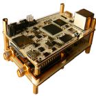 RAIN SDR An Open Source SDR Platform Base on ZYNQ SoC and MYRIAD
SNOW SDR is a low-cost
open source software defined radio platform based on
Xilinx ZYNQ SoC and MYRIAD RF module. It include
Giga Ethernet, USB OTG, HDMI, SDIO and USB-UART.
SNOW SDR is equipped an MYRIAD module that support
300MHz~ 3.8GHz, 28MHz BW application, such as WiFi,
LTE or WiMax.
Key Features Baseband Part: 1ЎўXilinx Zynq-7010/7020 EPP in the CLG400 package Dual ARM® Cortex™-A9 MPCore with CoreSight and NEON™ running at up to 677 MHz Artix-7 28 nm FPGA fabric as programmable user logic 2Ўў512MB DDR3 SDRAM and 4Gb NAND FLASH Memory 3ЎўGigabit Ethernet 4ЎўUSB-UART 5ЎўUSB 2.0 OTG support USB Strorage 6ЎўHDMI support 1080p Display 7ЎўMicro TF Card Connector support up to 8G card 8Ўў2 switches and 2 LEDs 9ЎўSingle 5V supply or USB power 10ЎўMode select switches
RF Part: 1ЎўSingle chip transceiver covering 0.3-3.8GHz frequency range 2ЎўDigital interface to baseband with integrated 12 bit D/A and A/D converters 3ЎўFully differential baseband signals 4ЎўProgrammable modulation bandwidth: 1.5, 1.75, 2.5, 2.75, 3, 3.84, 5, 5.5, 6, 7,8.75, 10, 12, 14, 20 and 28MHz 5ЎўSupports both TDD and FDD operation modes
HD Video Transformation Reference Design 1Ўў Support BPSK/QPSK/16QAM/64QAM 2Ўў Bitrates up to 54Mbps@20MHz BW 3Ўў FDD and TDD mode 4Ўў Frequency range cover 300MHz-3.8GHz
What's Included In This Development Kit 1ЎўSNOW SDR Board featuring the XC7Z010CLG400 AP SoC 2ЎўReference Designs, Design Examples, and Demos 3ЎўBoard Design Files, including schematic files 4ЎўAntenna support 433MHz ISM Band 5ЎўPower supply module 6ЎўSD card pre-installed firmware support Matlab and GNU Radio Targeted Applications 1ЎўSoftware Defined Radio 2ЎўFemtocell and Picocell base stations 3ЎўBroadband wireless communication devices for TV WhiteSpace/WCDMA/LTE/ GSM/ CDMA2000/WiFi 4ЎўResearch and Education on wireless
№©УҰLIMEөДҝӘ·ўМЧјю
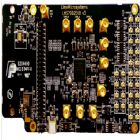 ҝӘ·ўМЧјюРНәЕОӘЈәMyriad LMS7002M Ј¬ UWCT Myriad Ј¬ UWCT LMS7002M Ј¬UWCT Cyclone IV©\LM , LMS7002M EVB°е
A. Connects to
PCs and laptops via USB
The Lime Development System is a comprehensive hardware and software combination that allows users to evolve and refine a wireless sub-system. It can be combined with a baseband processor such as an FPGA or DSP processor to develop a comprehensive wireless solution. The EVB7 module is a high-speed wireless communication module, based on the LMS7002M fully programmable RF transceiver. It is designed to support 2G, 3G, 4G/LTE radio systems with both time-division duplex (TDD) and frequency-division duplex (FDD) applications, M2M and software defined radios. The wireless communication module covers the frequency range of 100 kHz to 3.8 GHz, including licensed and unlicensed bands. The channel bandwidth is programmable from less than 100 kHz to 108 MHz through a combination of analog and digital filtering via the easy-to-use GUI software. The EVB7 provides system designers with the ability to connect the board to any type of baseband, FPGA or CPU and allow them to implement their ideas for various wireless communication applications. This document describes how to make a quick start with the LMS7002M using the EVB7 module. Section 2 begins by listing the contents of the Quick Start kit. Section 3 gives a general description of the evaluation board features. Section 4 describes the procedure for obtaining and installing the LMS7002M control software Ў°Control LMS7002MЎұ for both Windows and Linux platforms. Section 5 describes how to connect and use the EVB and LMS7002M control software Ў°Control LMS7002MЎұ for the Quick Start example configurations. Section 6 describes in detail the EVB connectors and hardware options. Section 7 describes in detail how to use the LMS7002M control software Ў°Control LMS7002MЎұ. Section 8.1 describes calibration procedures. Appendix 1 details the recommended test and measurement equipment, and how toset up the test equipment to work with EVB7 and the LMS7002M.
ҙъАн LIME LMS7002MЛ«КХ·ўЖч
ЧЬҪбМШРФ
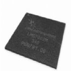
LMS6002DFN new zipper
ЧоРВөДLMS6002DFN new zipper ЧоРВөДLMS6002DFN
new zipper
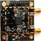
Myriad-RF 1 (Reference Board)
lms6002d board
Myriad-RFКЗТ»ӮҖй_·ЕФҙҙaн—ДҝЈ¬ҝЙУГҒнЧцҹoҫҖ°lХ№ФӯРНЈ¬ТФј°„“ФміцҝЙЕдЦГКҪҹoҫҖЖҪМЁ,
ҝЙ‘ӘУГм¶ҺЧәхәӯЙwЛщУРҳЛңКНЁУҚҳЛңКј°оlВКЎЈ Myriad-RFКЗТ»үKөНғr°е(ПаҢҰРФ¶шСФ)ҝЙТФУЙй_·Е…ўҝјФOУӢЛщСuФмЈ¬ЗТ»щм¶ТЧм¶К№УГөДУІуwј°ЬӣуwЖҪМЁЎЈ
Myriad RF
әНЮDҪУ°еБРЕeФЪПВ·Ҫ,ьc“фПВ·ҪөДҫWВ·ЯBҪY,ҝЙТФИЎөГёь¶аMyriad RF,ЮDҪУ°еәНKiCADФOУӢҷn°ё
2012 °ЛФВ24М–,AZIOіЙ№Ұ®aіцөЪТ»Ж¬Myriad-RF,УҶЩҸMyriad-RF(USD$299)
,ПВЭdMyriad RF KiCADҷn°ёЎЈMyriad-RFКЗТ»ӮҖ¶аоl¶О,¶аҢ’оlҳЛңКөДЙдоlлҠВ·°е,
ФЪLIMEөДКХ°lҶОҫ§Ж¬LMS6002D»щөAЙПҪЁҳӢФOУӢ¶шіЙ,ҙоЭdТ»ӮҖЙдоlоlҢ’Э”Ил,
Т»ӮҖЙдоlоlҢ’Э”іцәН”өО»»щоlҪйГж, ЎЈ Myriad-RFКЗТ»ӮҖЦ§Ф®¶аоl¶О,¶аҢ’оlҳЛңКөДЙдоlлҠВ·°е,ФЪLIME
Microsystems ПИЯM
өДКХ°lҶОҫ§Ж¬LMS6002D»щөAЙПҪЁҳӢФOУӢ¶шіЙ,ЎЈҙоЭdТ»ӮҖҢ’оlЙдоlЭ”Ил,
Т»ӮҖҢ’оlЙдоlЭ”іц,әНҪЁҳӢФЪЯBҪУЖчFX10A-80PөДҳЛңКПВөД”өО»»щоlҪйГжЎЈMyriad-
RFН¬•rТІМṩʹУГХЯлҠФҙЭ”Ил,Reference
Clock,”өО»I/QЭ”іц/Э”Ил,SPIҪйГжЯBҪУөДҪУД_ЎЈ
Ль°ьә¬БЛЯBҪУөҪЛщУРҝЙУГөД»щоlҫ§Ж¬ҪMТФј° FPGA,»тКЗӘҡБўЯ\ЧчДЈКҪЛщРиөДТ»ЗРЎЈ
Myriad-RF
ҝЙјУЛЩј°УРР§өДЧҢй_°lХЯНкіЙФЪҹoҫҖНЁУҚЙПёчКҪёчҳУөД‘ӘУГ®aЖ·,МṩёьУРҸ—РФөДҪвӣQ·Ҫ°ёЎЈ
БнНв,ФOУӢИЛҶTҝЙТФлSРДЛщУыөДАыУГТСй_°lНкіЙөДлҠВ·°е,ЯMРРРЮёДј°СuФм,јУЛЩ®aЖ·НкіЙөД•rйgЎЈ
лҠФҙ Myriad-RFҝЙҪӣУЙ”өО»ҪйГжЯBҪУЖч»тНвІҝлҠФҙ№©лҠ,лҠФҙ№©лҠ·ҪКҪһйКЦ„УЯx“сЎЈ
НвІҝлҠФҙұШнҡҝЙМṩлҠБч800mA,Из№ыөНм¶800mAлҠВ·°е•юІ»·Җ¶ЁЎЈЧоҙулҠүәЦөһй6V
лҠФҙҪУД_өДФ”јҡ”ўКцMyriad-RF development
manual. Э”іцәНЭ”Ил
Э”іцәНЭ”ИлПВБРөДұнёсМṩЦчТӘөДЭ”Илј°Э”іцЕдЦГ,ЯBҪУЖчөДЕдЦГј°ГиКц,Myriad-
RFЙПөДX3әНX4һйоҗұИІо·ЦIQУҚМ–ҪйГж,X6әНX7
·Ц„eһйЙдоlҪУКХЭ”Илј°°lЙдЭ”іц,
ҲDЖ¬ЙПТСЗеіюҳЛКҫіцҒнЎЈлҠВ·°еұ»Х{ХыөҪЦ§Ф®BAND 1(Tx
2140MHzәНRX 1950MHz)әНоlҢ’ЧчҳIЎЈ
НёЯ^ҝШЦЖҪӣУЙЯBҪУЖчX3 ЙПөД GPIO,З°¶ЛВ·ҸҪЗР“QЖчҝЙҝШЦЖЯx“сҪУКХЖчЭ”ИләН°lЛНЖчЭ”іцВ·ҸҪЎЈ
Ф”јҡөДФOЦГУҚПўХҲ…ўҝјХВ№қ3.7 НЁУҚ ҪӣУЙSPIҪйГжҝШЦЖLMS6002D•әҙжЖч,SPIҪйГжҝЙУЙX3”өО»ҪУД_»тX9НвІҝҪУД_ҒнФOУҶ
LMS6002•әҙжЖчКЗНёЯ^SPIҪйГжҒнҝШЦЖЎЈSPIҪйГжҝЙУЙX3”өО»ҪУД_»тX9НвІҝҪУД_ҒнФOУҶЎЈ
ФO¶ЁЕдЦГ Myriad-RFлҠВ·°еКЗоAПИЕдЦГК№УГФЪUMTS
band-1,ЧоіЈұ»К№УГ3GНЁУҚөДФOӮдЙПЎЈ
ЯBҪУЙПлҠДXҫНҝЙТФЕдЦГЯ\ЧчИОәОКЦҷCөДоlҺ§»тҳЛңКЎЈҝЙТФҪеУЙК№УГй_·ЕФҙҙaөДҲDРОҪйГжіМКҪҒнФO
¶Ё LMS6002 •әҙжЖч,НкіЙЛщРиөДоlВКЎўФцТжТФј°оlҢ’ҒнЯ_іЙЎЈ
EESO-001 LMS6002DFN ІвКФөЧ°е
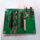
EESO-001 LMS6002DFN ІвКФөЧ°е
Myriad-RF 1 (Reference
Board) ЙдЖөІвКФ°е
ҙъАнІъЖ·
НЖіцТ»ҝоПЦіЎҝЙұаіМЈЁProgramming
on-the-flyЈ©
ЙдЖө°еMYRIADRF
LMS6002DҫЯУРТФПВУЕөгЈә
ЎЎ
The MyriadЁCRF 1 board is
a multi-band,
multi-standard RF
module, based on the
state of the art
LMS6002D transceiver IC
by Lime Microsystems. It
has one RF broadband
output, one RF broadband
input with digital
baseband interface,
established via standard
connector FX10A-80P. The
board also provides the
user with pin headers
for power supply,
reference clock, analog
I/Q input/output and SPI
interface connections.
It contains everything
needed for it to be
connected to baseband
(BB) chipsets, FPGAs or
to run in an standalone
mode.
ЎЎ
The Myriad-RF 1 board
enables developers
implement their products
for a wide variety of
wireless communication
applications quickly and
efficiently, given the
flexibility of the
solution. In addition,
the designer can make
use of the freely
available ready-made
board implementation,
modify and manufacture
to accelerate the
development time.
ЎЎ
Summary
ЎЎ
Transceiver
LMS6002D
ЎЎ
RF Bandwidth (BW)
300 MHz to
3800 MHz
ЎЎ
Baseband BW
Programmable (16
selections); 0.75 ЁC 14
MHz, Bypass mode
ЎЎ
RF Module Control
Via SPI
interface
ЎЎ
Analog Inputs
I/Q
differential analog
input for transmitter
ЎЎ
Analog Outputs
I/Q
differential analog
output from receiver
ЎЎ
Reference Clock
frequency 23 ЁC
41 MHz
ЎЎ
Input Voltage
5
V(recommended)
ЎЎ
Power
ЎЎ
The MyriadЁCRF 1 board
can be powered via the
digital interface
connector or using an
external power supply.
The power source is
selected manually.
ЎЎ
External power supply
has to be able to supply
800 mA current, below
this the board may be
unstable. The maximum
voltage level is 6 V.
ЎЎ
The power pins are
described in detailed
the Myriad-RF
development manual.
ЎЎ
Output and Input
ЎЎ
The figure and table
below provide key
Input/Output
configurations,
connector assignments
and descriptions. The
analog differential IQ
interface is available
on Myriad-RF board and
provided via X3 and X4
connectors. X6 and X7
are the RF connectors
for receive input and
transmitter output,
clearly marked in the
picture. The board is
tuned to support band 1
(Tx 2140 MHz and Rx 1950
MHz) as well as
broadband operation. The
front end switches are
configurable for
selecting Receiver
inputs and Transmitter
outputs via GPIOЎҜs which
in turn can be
controlled via the X3
connector.
ЎЎ
For a detailed
information on the
setup, please refer to
section 3.7 of the
Myriad-RF development
manual.
ЎЎ
Connector Name
Description
ЎЎ
X2 +5 V supply
External +5 V
supply.
ЎЎ
X3 Digital I/O
The FX10A-80P
is a standard connector
used to interface
the RF board
directly to interface
board or any other
baseband board.
ЎЎ
X4 TX Analog I/Q
Connector
used to supply Transmit
analog I/Q signals.
ЎЎ
X5 RX Analog I/Q
Connector
used to measure Receive
analog I/Q signals.
ЎЎ
X6 RXTEST
SMA connector
provides connection to
low band or high
band RX
input. Requires
preselected RF switch
configuration.
ЎЎ
X7 TXTEST
SMA connector
that provides connection
to low band or
high band
TX output. Requires
preselected RF switch
configuration.
ЎЎ
X8 Ext ЁC CLK
Connector used
to supply PLL clock
externally Please refer
to section 3.7 for
more information.
ЎЎ
X9 Ext ЁC SPI
Connector used
to control LMS6002DFN
SPI registers
externally. SPI
register are controlled
via X3 connector.
Please refer to
section 3.6 for more
information.
ЎЎ
Communication
ЎЎ
The LMS6002D register
are controlled via SPI
interface. The SPI
interface can be
established via digital
connector X3 or external
connector X9.
ЎЎ
Configuration
ЎЎ
The Myriad-RF 1 board is
pre-configured to work
on UMTS band-1, the most
common band used by 3G
communications
equipment. By connecting
the device to a computer
it can be configured to
run on any mobile
frequency band or
standard. This can be
done by setting up the
LMS6002D registers to
the required frequency,
gain or BB bandwidth
setting using an open
source graphical user
interface (GUI)
ЎЎ
Physical dimensions
ЎЎ
The Myriad-RF 1 board
measures 5ЎБ5.5cm with
the SMA connectors. Four
screw holes allow the
board to be attached to
a surface or casing.
|
|
ЎЎ
ёь¶аІъЖ·Злҝҙұҫ№«ЛҫІъЖ·ЧЁУГПъКЫНшХҫ:
SSTKJЦР№ъҙ«ёРЖчҝЖјјРЕПўНшЈәhttp://www.sensor-ic.com/
SSTKJ№ӨҝШ°І·АНшЈәhttp://www.pc-ps.net/
SSTKJөзЧУ ФӘЖчјюНшЈәhttp://www.sunstare.com/
SSTKJОўІЁ№вөзІъЖ·Нш:HTTP://www.rfoe.net/
SSTKJПы·СөзЧУІъЖ·Нш://www.icasic.com/
SSTKJКөТөҝЖјјІъЖ·Нш://www.sunstars.cn/
ҙ«ёРЖчПъКЫИИПЯЈә
өШЦ·ЈәЙоЫЪКРёЈМпЗшёЈ»ӘВ·ёЈЗмҪЦәиНјҙуПГ9732КТ
өз»°Јә0755-83376489 83376549 83607652 83370250 83370251
ҙ«ХжЈә0755-83376182 ЈЁ0Ј©13902971329 MSN: SUNS8888@hotmail.com
УКұаЈә518033 E-mail:szss20@163.com QQ: 195847376
ЙоЫЪИьёсХ№ПъІҝЈәЙоЫЪ»ӘЗҝұұВ·ИьёсөзЧУКРіЎ9583әЕ өз»°Јә0755-83665529 13823648918 FAX:0755-83376182
јјКхЦ§іЦ: 0755-83394033 13501568376
»¶УӯЛчИЎГв·СПкПёЧКБПЎўЙијЖЦёДПәН№вЕМ Ј»ІъЖ··І¶аЈ¬ОҙДЬҫЎВјЈ¬»¶УӯАҙөзІйСҜЎЈ
ұұҫ©·Ц№«ЛҫЈәұұҫ©әЈөнЗшЦӘҙәВ·132әЕЦР·ўөзЧУҙуПГ3097әЕ
TELЈә4006579498 18927445855 13823791822 FAXЈә010-62543996
ЙПәЈ·Ц№«ЛҫЈәЙПәЈКРұұҫ©¶«В·668әЕЙПәЈЩҗёсөзЧУКРіЎөШПВТ»ІгD25әЕ
TELЈә4006571586 56703037 13823676822 FAXЈә021-56703037
Оч°І·Ц№«ЛҫЈәОч°ІёЯРВҝӘ·ўЗш20Лщ(ЦР№ъөзЧУҝЖјјјҜНЕөјәҪјјКхСРҫҝЛщ)
ЎЎЎЎЎЎЎЎЎЎ Оч°ІАН¶ҜДПВ·88әЕөзЧУЙМіЗ¶юВҘD23әЕ
TELЈә4006572198 13072977981 FAX:029-77678271